Sunday, December 2, 2012

Virtual Networks : The way ahead - 2

In this post, I will start focusing on Layer2 Multipath technologies those became prominent with new changes in Data Center enviroment with the advent of virtualization. I will focus on MLAG technology in this post.

L2 Multi-Path : MLAG
Probably, everyone who puts their hands/brains around a switch/router knows about LAG(Link Aggregation) which was proposed as an IEEE standard  IEEE 802.3ad.  Before we go into what is M-LAG and how it is different from LAG and what are the things M-LAG borrows from LAG, I would like to first remember what LAG means and how it works.

What is LAG and how it works?

Actually, Link aggregation is pretty old technology that allows you to bond multiple parallel links into a single virtual link (from the STP perspective). With parallel links being replaced by a single link, STP detects no loops and all the physical links can be fully utilized.

Link Aggregation Control Protocol LACP (IEEE 802.3ad) detects multiple links available between two devices and configures them to use as an aggregate bandwidth. The two sides detect the availability of the other side by sending LACP PDUs. One end is an Actor, while the other end is the Partner. LACP PDUs are sent at a regular instance to multicast MAC address 01:80:C2:00:00:02. During LACP negotiation, the triplet {Admin Key, System ID, System Priority} identifies the LAG instance. So, for a LAG, all participating ports on that device must have the same triplet value.

LACP has two modes- Active and Passive. In Active mode, the ports send out LACP PDUs to seek Partners after the physical link comes UP. In Passive mode, the ports send out LACP PDUs only in response to reception of LACP PDUs from remote side. When LAG is manually configured, it is the responsibility of the operator to ensure that the configuration is same on both endpoints. The capabilities of the ports within a LAG must be consistent i.e speed/duplex must match on all ports, auto-negotiation must be disabled when LACP is used.

There are 2 reasons to implement LAG- a) to improve link reliability i.e. if one of the links in the LAG goes down, the LAG is still operationally UP. b) to expand the bandwidth i.e. the available bandwidth in LAG is the summation of the bandwidth of all LAG member links.

To keep traffic flow in sequence, traffic is distributed over the links in the LAG using a hashing algorithm called per-flow based hashing algorithm. Hashing is an operation of transforming an input into a fixed value or key. In Ethernet LAG, the hash input can be either source/destination MAC addresses, or source/destination IP addresses, or both. Even Layer 4 header can be added to the hashing algorithm criteria. This results in the id of the egress port to which the flow is sent.
So, this is how a LAG works…

What is M-LAG and how it works?

Multi-Chassis LAG is an emerging technology that is mainly meant to solve problems raised because of inefficiencies in Spanning-Tree protocol (STP) in data center environments. Normally, In Link Aggregation topologies, two devices involved are directly connected. Imagine you could pretend two physical boxes use a single control plane and coordinated switching fabrics.. then the links terminated on two physical boxes actually terminate within the same control plane and you could aggregate them. Welcome to the wonderful world of Multi-Chassis Link Aggregation (MLAG).
MLAG nicely solves the STP problem: no bandwidth is wasted and close-to-full redundancy is retained.
MLAG is the simplest L2 multipathing strategy that vendors offer now a days. MLAG. MLAG allows multiple physical switches to appear to other devices on a network as a single switch, although each switch is still managed independently. This allows you to multihome a physical host to each of the switches in the MLAG group while actively forwarding on all links, instead of having some links be active, and some wasted while they lie dormant in a standby state. LACP (802.3ad) is commonly used to arbitrate these links.

Let me go in detail about this with a picture:
Device 1 treats the two links as  regular Link Aggregation (LAG). Devices 2 and 3 participate in the MLAG to create the perception of a LAG. In effect, MLAG adds multi-path capability to traditional LAG, albeit where the number of paths is generally limited to 2. With MLAG, both links that are dual homed from Device 1 can be actively forwarding traffic. If one device in the MLAG fails, for example, if Device 3 fails, traffic is redistributed back to Device 2, thus allowing for both device and link level redundancy while utilizing both active links. MLAG can be used in conjunction with LAG and other existing technologies. The limitation of two paths for an MLAG isn’t really such a big limitation today, because many DC networks today are designed using dual uplinks, i.e.,  in  a large cross section of current deployments, you don’t have more than two uplinks to multi-path over anyway.

“proprietary” implementations of MLAG

MLAG implementations are mostly proprietary. The “proprietariness” of MLAG is confined to the two switches in the tier that is offering the MLAG, i.e., Device 2 and Device 3 in the picture above need to be from the same vendor. Device 1, on the other hand, simply treats both the ports as a regular LAG and as such could come from another vendor. So for example, MLAG can be used in conjunction with NIC teaming where Device 1 could be a server  which can be dual homed to two switches operating as an MLAG. MLAG can also be used in conjunction with upcoming 
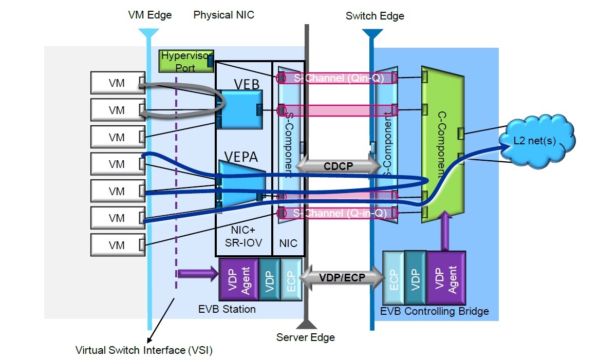
standards-based technologies such as VEPA to switch VMs directly in the network over active-active paths from the server. For knowing what is VEPA technology, you can always look into my previous post.

Normally How do Device 2 and Device 3 communicate so that they are connected to a single partner and it is MLAG?

So, the  Million dollar question – How do these device 2 and device 3 in the above example come to know that they are connected to an MLAG? These two devices have to advertise the same LACP triplet  {Admin Key, System ID, System Priority}  to the partner device 1 so that the connection stays intact.  Device 2 and Device 3 normally follow a protocol which is implementation specific/vendor specific. However, IEEE has a standard for this feature defined in the standard IEEE 802.1AX. This comes as a revision to Link Aggregation. However, the communication mechanism between devices is vendor specific and is not quoted in IEEE standard specified above.For example, In an industry implementation followed by Alcatel-Lucent in such topology, MC-LAG control protocol information is exchanged between device 2 and device 3. This exchange results in active/standby selection, and ensures only one of the two device's(device 2/device3) ports are active and carrying traffic. MC-LAG control protocol runs only between MC-LAG peers. The protocol uses UDP packets (destination port 1025) and can use MD5 for authentication. It is used as a keep-alive to ensure peer device is active. It is also used to synchronize LAG parameters. MC-LAG peers are not required to be directly connected to each other. Also, if MC-LAG peer is not found, both devices (device 2 and device3) become active. Thus, the device1 brings up all links for the LAG.

  Why M-LAG is needed in Data Center Networks? Why normal LAG will not help?

Why M-LAG is needed in DC networks? What is first the need for these kind of multipath configurations? That points me to where I started my blog. Impact of server virtualization is one of the prime reasons for the situation. IT administrators are looking to pack several virtual machines(VMs) on a physical server in order to reduce cost and power consumption.  As more VMs are packed on a single server, the bandwidth demands from the server edge, all the way to the core of the network, are growing at a rapid pace. Additionally with more virtual machines on a single server, the redundancy and resiliency requirements from the server edge to the core of the network are increasing.
Traditionally, the approach to increasing bandwidth from the server to the network edge has been to add more Net­work Interface Cards (NICs) and use Link Aggregation (LAG) or “NIC teaming” as it is commonly called to bond links to achieve higher bandwidth. Something as shown in the following figure can be visualized for this scenario:


If any of the links in the group of aggregated links fails, the traffic load is redistributed among the remaining links. Link aggregation provides a simpler and easier way to both increase bandwidth and add resiliency. Link aggregation is also commonly used between two switches to increase bandwidth and resiliency. How­ever, in both cases, link aggregation works only between two individual devices, for example switch to switch, or server to switch. If any one of the devices on either end of the link aggregated group (or trunk as it is also called) fails, then there is complete loss of connectivity. So, we need device level redundancy along with link level redundancy. As link level redundancy can be achieved with LAG, let us explore some options to have device level redundancy.

Layer3 routing protocols –  for device level redundancy

Various router redundancy protocols such as VRRP, in conjunction with interior gateway protocols such as OSPF, provide adequate resiliency, failover and redundancy in the net­work. These kind of mechanisms are used for device level redundancy in the network. Where Layer 3 routing and segmentation is deployed in the network. However, as you can see from my previous post, virtualization technologies are driving current Layer 2 topologies to go “flatter” and “faster”. As virtual machine movement today is typically restricted to within a subnet boundary, device level redundancy through Layer3 protocols may not be a good option.

How current STP may not be very useful here???

In Layer 2 topologies, protocols such as the spanning tree protocol have typically provided redundancy around both link and device failures.
Spanning tree protocol works by blocking ports on redundant paths so that all nodes in the network are reachable through a single path. If a device or a link failure occurs, based on the spanning tree algorithm, a selective redundant path or paths are opened up to allow traffic to flow, while still reducing the topology to a tree structure which prevents loops.

STP with Link Aggregation(LAG):

Spanning tree protocol can be used in combination with link aggregation where links between two nodes – such as switch to switch connections – can be aggregated using link aggregation to increase bandwidth and resiliency between nodes or devices. Spanning tree would typically treat the aggregated link as a single logical port in its calcu­lations to come up with a loop free topology. See such normal STP+LAG combination topology:


So, how MLAG helps here??

If one read above blog content carefully, it all boils down to a point – we need a provision that gives device level redundancy along with link level redundancy. We reached this situation because spanning tree protocol does not provide this and this is a shortcoming of STP. . But highly virtualized data centers require high performance as well as resiliency as mentioned earlier in this post. One way to solve such requirements is to extend the link-level redundancy capabilities of link aggregation and add support for device-level redundan­cy. This can be accomplished by allowing one end of the link aggregated port group to be dual-homed into two different devices to provide device-level redundancy. The other end of the group is still single homed into a single device. Let us examine this topology through a figure:

  • Device 1 => No change in LAG behavior. LAG hashing distributes traffic as before.
  •   Device 2 & Device 3 => Communicate to each other through an ISL. ISL link can also be a LAG interface. These two devices communicate each other through a proprietary protocol so that they create a perception that together they form a normal Link aggregation group towards Device 1. Device 2 and Device 3 communicate through ISL link so that learning, forwarding, bridging happens without any loops.
  •   Communication protocol between Device 2 and Device 3 => proprietary
  •   Device 2 and Device 3 should belong to the same vendor
  •   Device 1 can be a switch or server and need not be from the same vendor as that of Device 2 and Device 3. Device 1 does not participate in any proprietary protocol.
  •   If link from device 1 goes down, an alternative path is chosen normally as if one of the links in a normal LAG goes down.
  •  If any links on Device 2 or Device 3 go down, proprietary communication mechanism between Device 2 and Device 3 decide upon providing alternate connectivity as if there is a single Aggregation group among them as a normal LAG.

Vendor Offerings

This MLAG service is offered by prominent data center vendors among which most famous are:

CISCO’s Virtual Port Channel – CISCO provides MLAG feature by a name called Virtual Port Channel. This feature is available in Nexus 7000 and Nexus 5000 switches. Cisco supports configuring two switches into a Virtual Port Channel(vPC) domain.
Arista’s Multi-Chassis Link Aggregation – This feature is implemented in Arista’s EOS product and is present across Arista’s product lines. Here two switches can participate in an MLAG.
Avaya’s Split Multi Link Trunking(SMLT) – Avaya supports Split Multi-Link Trunking feature for the Ethernet Routing Switch 8600, 8300, 5x00, and 1600 series. Switches are deployed as SMLT pairs in a cluster. 
Exterme Networks Multi System LAG – Extreme Networks supports Multi System LAG feature in order to join two switches to form an MLAG pair.

Advantages of MLAG 

  •  Can be built on existing LAG
  •  Simple Software upgrade on the existing infrastructure can bring MLAG feature

Disadvantages of MLAG

  • one of the member links, meaning that adding  physical link to an MLAG bundle doesn’t always result in a commensurate bandwidth boost.
  • you can’t link switches from two vendors to form an MLAG group. For example, you could uplink a Cisco switch into an Arista MLAG pair, but you won’t be able to have an Arista switch and a Cisco switch form the MLAG pair.
  • It’s also important to understand that an MLAG pair is still two physical switches with minds of their own. Therefore, complex communication must be maintained between the pair at all times to ensure a stable, loop-free topology. Understanding how an MLAG pair behaves when communication is lost between the two members is a key design element one will need to review with vendor from which the member is bought.
  [In my next post, I will take up other L2 Multi-Path technologies]

Saturday, December 1, 2012

Virtual Networks : The Way Ahead - 1


Virtualization changed server market dramatically. Dramatic enough to raise a new market force called VmWare in server market.  Apart from changing marketing dynamics, virtualization started changing the school of thought about information transfer into which networking market got admission lately.

 In the past, network designers built fat-tree topologies in which traffic traveled in a north-south orientation up and down the tree. That’s an adequate design for client-facing traffic and workloads that don’t move. A smart designer could put systems that need to talk to one another nearby and reduce the amount of traffic flowing up and down the tree.
Networks were always determined by the Spanning Tree Protocol that forced a tree like structure from core to edge. Today, we refer to this as North/South Alignment because traffic flows were predominantly Server to LAN Core to WAN Core to WAN Edge to Client.
Virtualization breaks this paradigm. Virtual machines are talking to other VMs in other racks and rows in an east-west fashion. And VMs can move to unpredictable data center locations. A designer can’t know where a workload is at any given time, because it’s no longer physically constrained. In that world, the fat tree fails at scale.  Also, Typical Spanning-Tree topologies would fail as well.  Alternatively L2 Multi-Path (L2MP) technologies are replacing Spanning-Tree. 


Today’s network architects and engineers have a multitude of options to meet demands raised because of virtualization. I would like to categorize at significant data center network technologies in three major categories:

(i) Layer 2 multi-path
(ii)Layer 2 extension 
(iii)software-defined networking.

I will try to take a stab at these technologies once.  I will try to go in deep about these in my next-posts.


L2 Multi-Path
Layer 2 multi-path tackles the built-in limitations of Spanning Tree Protocol by enabling all links to forward traffic while ensuring redundancy and eliminating loops that could take down a network. While some of these L2 Multipath technologies are standards/work group based, come are proprietary. IETF has a workgroup which introduced TRILL(Trasparent Interconnection of Lots of Links) whereas IEEE has a standard 802.1aq known as SPB(Shortest Path Bridging). Emerging protocols such as TRILL and SPB let designers create meshes or fabrics that enable traffic to take the shortest path between switches.
Proprietary Options include MLAG and virtual chassis, which allow multiple switches to act like a single device.

L2 Extension
One of the reasons for Server Virtualization becoming prominent was it makes the server movement a cake walk. Virtual Machines can be moved across servers without any physical movement. VM movement has some problems to be solved in which case L2 Extension technologies are discovered. Layer 2 extension allows physically separate data centers to be linked into a Layer 2 domain across Layer 3 boundaries. Originally aimed at carrier networks(think VPLS and Q-in-Q, among others), some Layer 2 extension protocols are appearing the data center because they support the ability to move VMs from one data center to another, an ideal capability for load sharing, business continuity and disaster recovery. We look at Cisco’s Overlay Transport Virtualization, the Virtual Extensible Local Area Network(VXLAN), Network Virtualization using Generic Routing Encapsulation(NVGRE) and Stateless Transport Tunneling(STT).

Software Defined Networking(SDN)
Software-defined networking is emerging as an alternative to the traditional switch model in which the control plane resides within each switch. While SDN and OpenFlow are not synonymous, OpenFlow demonstrates SDN’s promise: take the decision-making away from the switches and routers, and move it into a centralized controller that will tell the network as a whole how to forward traffic, allowing for more flexible networks that can respond in near real time to changing conditions. It also doesn’t hurt that Open-Flow and SDN have the potential to make networking gear less expensive.This can make the network more flexible and better able to respond to changing demands. In addition to SDN,in my next posts, I will try to dig into OpenFlow, a new protocol for communicating between switches and a controller. In next posts, I will try to explain the potential implicationsof SDN and OpenFlow and evaluate its impact on data center networks.


[In my next post, I will take a deep dive on L2 Multipath technolgies]

Monday, November 26, 2012

Data Center Transformation: Hierarchical Network to Flat Network


As I read literature on Data Center Networks with respect to enormous increase in data loads and virtualization of servers, I see that market is trending towards data center network architectures which are flat in nature. I hear a term called “Fabric” to refer to data center networks. In this post, I will try to express my understandings and opinions on this concept of transformation of Data center networks from 3-tier to flat.

Three-tier Network Architecture - Current Data center network

Network architecture that is dominant in current data centers is Three-tier network architecture.  Most of current data center networks are built on this architecture. By three tiers, we mean access switches/Top-of-Rack (ToR) switches, or modular/End-of-Row (EoR) switches that connect to servers and IP based storage. These access switches are connected via Ethernet to aggregation switches. The aggregation switches are connected into a set of core switches or routers that forward traffic flows from servers to an intranet and internet, and between the aggregation switches.  Typically this can be depicted as follows:


As you can see some blocked links, it is apparent that these links are blocked because of Spanning Tree Protocol (STP) running in the network.

For detailed connections with focus on Access(TOR/EOR) switches connected to servers, you can always refer to my previous post which shows a beautiful picture of interconnections.

In this 3-tier architecture, it is common that VLANs are constructed within access and aggregation switches, while layer 3 capabilities in the aggregation or core switches, route between them. Within the high-end data center market, where the number of servers is in the thousands to tens of thousands and east-west bandwidth(intra-server traffic) is significant, and also where applications need a single layer 2 domain, the existing Ethernet or Layer 2 capabilities within this tiered architecture do not meet emerging demands.  When I say, Layer 2 capabilities, I mainly refer to Spanning-Tree protocol which keeps the network connected without any loops. 

STP..STP…STP.. I thought it was good…what happened?

Radia Perlman created the Spanning Tree algorithm, which became part of the Spanning Tree Protocol (STP), to solve issues such as loops. Ms. Perlman certainly doesn’t need me to come to the defense of Spanning Tree–but I will. I like Spanning Tree, because it works. I would say that in at least 40% of the networks I see, Spanning Tree has never been changed from its default settings, but it keeps the network up, while at the same time providing some redundancy.
However, while STP solves significant problems,it also forces a network design that isn’t optimized for many of today’s data center requirements. For instance, STP paths are determined in a north-south tree, which forces traffic to flow from a top-of-rack switch out to a distribution switch and then back in again to another top-of-rack switch. By contrast, an eastwest path directly between the two top-of-rack switches would be more efficient, but this type of path isn’t allowed under STP. The original 802.1D Spanning Tree can take up to 52 seconds to fail to a redundant link. RSTP (802.1w) is much faster, but can still take up to 6 seconds to converge. It’s an improvement, but six seconds can still be an eternity in the data center.
                                                    

So, what is needed???

 The major problems that need to be solved in current networks which use spanning tree topologies are :
  1.     poor path optimization 
  2.     failover timing 
  3.     limited or expensive reachability 
  4.     latency.
Simply put, we need to be able to reach any machine, wherever it is in the network,while using the best path through the LAN to do so. This will lower latency, provide access to more bandwidth and provide better ROI for the network infrastructure in the data center. If a device fails, we want to recover immediately and reroute traffic to redundant links.

 How existing tiered architecture needs to be changed?

 One way to design a scalable data center fabric is often called a “fat-tree” and has two kinds of switches; one that connects servers and the second that connect switches creating a non-blocking, low latency fabric. We use the terms ‘leaf’ switch to denote server connecting switches and ‘spine’ to denote switches that connect leaf switches. Together, a leaf and spin architecture create a scalable data center fabric. Another design is to connect every switch together in a full mesh, with every server being one hop away from each other. I know a picture can help here quite a lot….


How this flat network helps in DC networks???

 The virtualization and consolidation of servers and workstations causes significant changes in network traffic, forcing IT to reconsider the traditional three-tier network design in favor of a flatter configuration. Tiered networks were designed to route traffic flows from the edge of the network through the core and back, which introduces choke points and delay while providing only rudimentary redundancy.

Enter the flat network. This approach, also called a fabric, allows for more paths through the network, and is better suited to the requirements of the data center, including the need to support virtualized networking, VM mobility, and high-priority storage traffic on the LAN such as iSCSI and FCoE. A flat network aims to minimize delay and maximize available bandwidth while providing the level of reachability demanded in a virtual world. 

Don’t think flat network is Eutopia…

It is all not ready made or ready to deploy... a flat network also requires some tradeoffs, including the need to rearchitect your data center LAN and adopt either new standards such as TRILL (Transparent Interconnection of Lots of Links) and SPB (Shortest Path Bridging),or proprietary, vendor-specific approaches. It is a debate on how many people in the industry are willing to go for this rearchitecture. I could access a survey in this regard:


Commercial Sample Leaf & Spine Architecture

A commercial Leaf and Spine architecture built using Dell Force10 switches can be shown as follows. In this design Force 10 products are used.
  • Spine Switches – 4 switches – Z9000 (32 x 40GE)
  • Leaf Switches – 32 switches – S4810 (48 x10GE)


You can see that each S4810 switch has connections to four Z9000 switches. That is, each switch in Leaf network has multiple paths(4 paths) to reach spine network. 


Conclusion….

 These kind of flat networks are being proposed now a days to solve problems with Traditional STP based data centers. While it is not a simple decision to go from 3-tier to flat network, flat networks are gaining momentum.  With server virtualization becoming more prominent in current data centers, several other technologies related to this Leaf & Spine architecture need to be considered  for evaluating whether a network needs to go flat or not…These technologies mainly include Layer2 Multipathing Technologies such as TRILL,SPB,M-LAG, VCS etc which changed equations of typical STP based topologies..Also need to understand several Layer Extension technologies which are gaining prominence because of virtualization – NVGRE, VXLAN, CISCO OTV.. Another buzzword now a days I see is SDN(Software Defined Networking).. All these aspects need to be understood thoroughly for adopting new generation virtual networks for Data Centers…

[My next post contains my take on virtual networks with emphasis on L2 Multipathing, L2 extension and SDN]


Monday, November 19, 2012

Impact of Server Virtualization on Networking - 5


Port extension Technology

 VEPA raised some issues which are being tackled by port extension technologies. There are two standards corresponding to port extension technologies – IEEE 802.1qbh and IEEE 802.1 BR. Among these, IEEE 802.1 qbh has been withdrawn by IEEE on September 10th, 2011 while IEEE 802.1 BR is active.

    Some years ago, Data center Networking got a new concept introduced by CISCO called – “Fabric Extenders”. Cisco used the term ‘fabric extender’ while IEEE uses terms ‘port extender’. Honestly, being marketing friendly – I like the term ‘fabric extender’. 
    
   Typically port extender technology connects Servers to Controlling switch(Edge switch) as shown follows:

Cisco’s proprietary technology used in its FEX products became the basis for 802.1Qbh, an IEEE draft that is supposed to standardize the port extender architecture.

The core ideas behind 802.1Qbh are very simple:
  • After power-up, the port extender finds its controlling bridge (connected to theupstream port)
  • Port extender tells the controlling bridge how many ports it has;
  • The controlling bridge creates a logical interface for each port extender port and associates a tag value with it;
  • Port extender tags all packets received trough its ports with tags assigned by the controlling bridge;
Here the concept of tags comes in order to segregate each logical interface.
The external network switch connects to an external port extender using logical E-channels .These logical channels appear as virtual ports in the external network switch. Because the port extender has limited functionality, the external network switch manages all the virtual ports and their associated traffic.

Port extenders either use existing proprietary Cisco technology with VN-tags or will use the upcoming E-tag from the draft IEEE 802.1 BR Port Extension specification. The E-tag is longer than the VN-tag. It has different field definitions and different field locations but serves the same purpose. 
Port extenders use the information in VN-tags or 802.1 BR E-tags to:

• Map the physical ports on the port extenders as virtual ports on the upstream switches

• Control how they forward frames to or from upstream switches

• Control how they replicate broadcast or multicast traffic

Here is a pic depicting both CISCO VN-Tag and E-Tag(802.1BR) 
So, How did Port Extender solve Network Management Visibility problem on VM traffic?
All this funda of Port extender started because with VEPA etc problem of management visibility into VM traffic came up. Introduction of Port Extension technology solves this problem by by reflecting all network traffic onto a central controlling bridge. This gives network administrators full access and control but at the cost of bandwidth and latency.
Hmmm...But.. There are problems with Port Extension Technologies
  1. Port extension technology adds one or more extra hops to the typical three-tier architecture and can magnify congestion problems
  2. As data centers support more clustered, virtualized, and cloud-based applications requiring high performance across hundreds or thousands of physical and virtual servers, port extension technology just seems to add cost and complexity.
  3. Remember that the pre-standard VN-tags and the IEEE 802.1-BR standard E-tags use different formats. If you adopt VN-tag solutions in your data center, you will have to develop transition strategies when future hardware changes to the IEEE 802.1-BR E-tag format.
Ok.. Now the conclusion
In past 5 posts, we discussed several aspects surrounding the impact of server virtualization on Networking. We Started with the fact that Servers with the virtue of Virtualization have hypervisor software inside them. This Hypervisor is adding another layer of software called Virtual Switch/Virtual Ethernet Bridge. This VSwitch also adds on complexities in terms of Network Management and VM mobility. Then we discussed further on different kinds of VEBs - Software VEBs and Hardware VEB(SR-IOV). Issues associated with vSwitches/VEBs are targeted to be solved through IEEE 802.1 qbg by the introduction of Edge Virtual Bridging through VEPA(Virtual Ethernet Port Aggregator) Technology and S-Channel(Multi-channel VEPA) technology. While IEEE 802.1qbg solved some problems of VSwitch, it did raise some issues which are tackled by IEEE 802.1qbh and IEEE 802.1br by introducing Port Extension Technology. While IEEE 802.1qbh was withdrawn last year, IEEE 802.1BR is active and it did solve some problems while introduced some other. So, it all comes to using these solutions effectively  as per use case. It also depends on how much IT budget we have and IT needs in terms of Server requirements.
Personally, I agree with what many experts in this area say -  Virtual switches won’t be going away anytime soon, but the configuration and management of these virtual network devices shouldn’t reside with the server team merely by virtue of their ownership of the underlying VM management platform. Until the technology allows virtual port management to be pulled into a comprehensive management tool, it means the network and server teams will have to share authority for the VM platform..

That ends my series of posts on "Impact of Server Virtualization on Networking" .


[I am thinking of topic for my next blog posts. Most probably I will take up the one which is interesting me now a days when I read literature on Data Center Networking.. I read quite a lot about leaf&Spine architecture, Data Center Fabric, Transformation of DC networks from Hierarchical nature to Flat.. And the most famous -  movement of traffic patterns from "North-South" to "East-West"]...

Tuesday, November 13, 2012

Impact of Server Virtualization on Networking - 4


Edge Virtual Bridging (EVB) - IEEE 802.1qbg

In my previous posts, we discussed on vSwitches/VEB and SR-IOV technologies. None of the devices built upon these technologies can achieve the level of network capabilities those are built into enterprise-class L2 data center switches. Obviously, L2 data center switches are feature-rich and volumes richer in terms of capabilities. To solve the management challenges with VEBs IEEE 802.1Qbg standard is being developed. The primary goals of EVB are to combine the best of software and hardware VEBs with the best of external L2 network switches.


VEPA (Virtual Ethernet Port Aggregator) : 

EVB is based on VEPA technology. This VEPA technology was proposed by HP and is taken as basis for IEEE 802.1qbg standard. First let us see what is standard VEPA. It is a way for virtual switches to send all traffic and forwarding decisions to the adjacent physical switch. This removes the burden of VM forwarding decisions and network operations from the host CPU. It also leverages the advanced management capabilities in the access or aggregation layer switches. Traffic between VMs within a virtualized server travels to the external switch and back through a reflective relay, or 180-degree turn( blue line shown in the following pic).


Do you see anything weird here? - Hairpinning

Packet sent from the same port is travelling to Edge Switch and is being received on the same port. Normally, Ethernet frames are not forwarded back out of the same interface they came in on. This action, called hairpinning, causes a loop in the network at the port. Normally, typical STP behavior prevents switch from forwarding a frame back down the port it was received on. But, for VEPA based EVB stuff, we need that phenomenon to happen. Simply, we need that hairpin turn to happen. So, some solution needs to be implemented in switch to allow such hairpin turn to be allowed.
EVB provides a standard way to solve the hairpinning problem.Basically, when a port on switch is configured as VEPA port, then standard proposes a negotiation mechanism between physical server and switch. With this negotiation, switch allows this hairpin turn.

Point to be noted here - Current Edge Switch infrastructure needs firmware update with this negotiation mechanism implemented in order to have hairpin forwarding to occur.

Good thing about VEPA based solution is that it does not require new tags and  involves only slight modifications to VEB operation, primarily in frame relay support. VEPA continues to use MAC addresses and standard IEEE 802.1Q VLAN tags as the basis for frame forwarding, but changes the forwarding rules slightly according to the base EVB requirements.

That's some briefing on EVB with VEPA technology. Let's explore positives and negatives about it..


  •  As processing overhead related to I/O traffic through vSwitch is reduced, server’s CPU and memory usage goes down. As adjacent switch performs advanced management functions as well, there is some scope to use NICs with low-cost circuitry.. Some cost cutting there…Right???
  •  Now, Control point for VMs is moved to Edge switch(TOR/EOR). So, If some company bought a TOR/EOR switch, they do not need to change any infrastructure. VEPA leverages existing investments made in DC Edge switching.
  • This VEPA can also be implemented in hypervisor/ SR-IOV nic. That gives flexibility to investors to have this either in server or Edge switch.


  •        VEPA enabled EVB technology still does not solve policy management problem across VMs that I mentioned in previous posts. So, policies attached to VMs can not still prevail during VM movement.
  •       VEPA can also  burden switches with more multicast and broadcast traffic(remember the negotiation mechanism that I mentioned for hairpinning mode).
  •      Switches can not mix VEPA, VEB and directly accessible ports on the same port. 


     S-Channel  Technology (Also referred as Multi-Channel VEPA): 

      So, we discussed what is VEPA here. But, this VEPA technology does not satisfy all use cases for which VEPA is meant. So, S-channel technology is introduced to satisfy some use case which basic VEPA did not satisfy:
  1.          Cases where Hypervisor functions require direct access to server NICs.
  2.         Cases where VMs directly would like to access Server NIC.
  3.         Cases where some VMs on the server would like to follow VEB mechanism and  other VMs on the server would like to follow VEPA. So, sharing the same server NIC to allow both VEB and VEPA connections in order to optimize local, VM-to-VM performance. 
  4.      Directly mapping a VM that requires promiscuous mode of operation.

     So, for solving the purpose of mapping different kinds of Virtual connections on same 
     server NIC connection, obvious choice is to explore existing ways of segregating 
     same physical connection into multiple logical connections. We already have such 
     solution - Service VLAN tags (S-Tags) from IEEE 802.1adThe VLAN tags let you logically separate traffic on a physical network connection or port (like a NIC device) into multiple channels. Each logical channel operates as an independent connection to the external network.

     S-channel also defines two new port-based, link-level protocols:

      Channel Discovery and Configuration Protocol (CDCP) allows the switch discovery and configuration of the virtual channels. CDCP uses Link-Layer Discovery Protocol (LLDP) and enhances it for servers and external switches.
     Virtual Switch Interface Discovery Protocol (VDP) and its underlying Edge Control Protocol (ECP) provide a virtual switch interface that sends the required attributes for physical and virtual connections to the external switch. VDP/ECP also lets the external switch validate connections and provides the appropriate resources.

      Obviously, a picture which depicts these agents in server as well as edge switch will make understanding much better. Picture uses 802.1qbg terminology. So, basically these protocols need to be implemented at both ends in order to have S-channel/Multi-channel VEPA to work.


  How customers(server Admins/Network admins) can use S-channel? 
      S-channel enables complex virtual network configurations in servers using VMs. You can assign each of the logical channels to any type of virtual switch (VEB, VEPA, or directly mapped to any virtual machine within the server). This lets IT architects match their application requirements with the design of their specific network infrastructure(something as shown in this pic)


      * VEB can be used for VM-to-VM traffic. VM-to-VM Traffic do not need to hairpin now.
     *  VEPA/EVB for management visibility of the VM-to-VM traffic. As traffic goes to edge switch, this traffic can be monitored/managed using edge switch monitoring/management technologies.
    

   How issues with VEPA are tackled?

   VEPA raised some issues which are being tackled by Bridge port extension technologies. There are two standards for this bridge port extension :

    IEEE 802.1qbh  - This uses CISCO's VNTAG mechanism
    IEEE 802.1BR   -  This uses E-Tag mechanism. 

     These will be explained in my next post.     

  [To be continued - Next post contains VN-Tag and E-Tag]